DBMS The Entity-Relationship Model
The Entity-Relationship (ER) model was originally proposed by Peter in 1976 as a way to unify the network and relational database views.
ER model is a conceptual data model that views the real world as entities and relationships. A basic component of the model is the Entity-Relationship diagram which is used to visually represents data objects.
An Entity–relationship model (ER model) describes the structure of a database with the help of a diagram, which is known as Entity Relationship Diagram (ER Diagram). An ER model is a design or blueprint of a database that can later be implemented as a database. The main components of E-R model are: entity set and relationship set.
ER model is:
It maps well to the relational model. The constructs used in the ER model can easily be transformed into relational tables.
It is simple and easy to understand with a minimum of training.
The model can be used by the database designer to communicate the design to the end user.
The model can be used as a design plan by the database developer to implement a data model in a specific database management software.
The ER model views the real world as a construct of entities and association between entities.
Entities
Entities are the principal data object about which information is to be collected. Entities are usually recognizable concepts, either concrete or abstract, such as person, places, things, or events which have relevance to the database. Some specific examples of entities are EMPLOYEES, PROJECTS, INVOICES. An entity is analogous to a table in the relational model.
Entities are classified as independent or dependent.
An independent entity is one that does not rely on another for identification.
A dependent entity is one that relies on another for identification.
An entity occurrence (also called an instance) is an individual occurrence of an entity. An occurrence is analogous to a row in the relational table.
Associative entities (also known as intersection entities) are entities used to associate two or more entities in order to reconcile a many-to-many relationship.
Subtypes entities are used in generalization hierarchies to represent a subset of instances of their parent entity, called the supertype, but which have attributes or relationships that apply only to the subset.
Relationships
A Relationship represents an association between two or more entities. An example of a relationship would be:
Employees are assigned to projects
Projects have subtasks
Departments manage one or more projects
Relationships are classified in terms of degree, connectivity, cardinality, and existence.
Attributes
Attributes describe the entity of which they are associated. Attributes are data objects that either identify or describe entities. Attributes that identify entities are called key attributes. Attributes that describe an entity are called non-key attributes. A particular instance of an attribute is a value. For example, "Jane R. Hathaway" is one value of the attribute Name. The domain of an attribute is the collection of all possible values an attribute can have. The domain of Name is a character string. Attributes can be classified as identifiers or descriptors. Identifiers, more commonly called keys, uniquely identify an instance of an entity. A descriptor describes a non-unique characteristic of an entity instance.
Degree of a Relationship
The degree of a relationship is the number of entities associated with the relationship. The n-ary relationship is the general form for degree n. Special cases are the binary, and ternary ,where the degree is 2, and 3, respectively.
A Relationship represents an association between two or more entities.
What is an Entity Relationship Diagram (ER Diagram)?
An ER diagram shows the relationship among entity sets. An entity set is a group of similar entities and these entities can have attributes. In terms of DBMS, an entity is a table or attribute of a table in database, so by showing relationship among tables and their attributes, ER diagram shows the complete logical structure of a database. Lets have a look at a simple ER diagram to understand this concept.
A simple ER Diagram
In the following diagram we have two entities Student and College and their relationship. The relationship between Student and College is many to one as a college can have many students however a student cannot study in multiple colleges at the same time. Student entity has attributes such as Stu_Id, Stu_Name & Stu_Addr and College entity has attributes such as Col_ID & Col_Name.
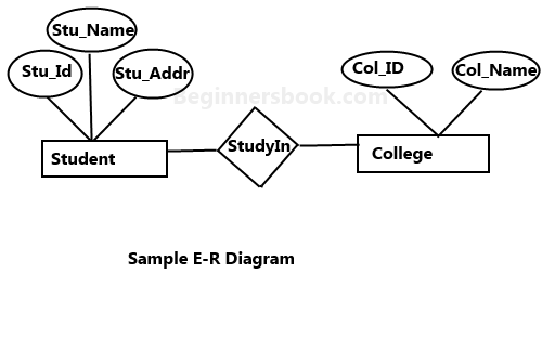
Rectangle: Represents Entity sets.
Ellipses: Attributes
Diamonds: Relationship Set
Lines: They link attributes to Entity Sets and Entity sets to Relationship Set
Double Ellipses: Multivalued Attributes
Dashed Ellipses: Derived Attributes
Double Rectangles: Weak Entity Sets
Double Lines: Total participation of an entity in a relationship set
Components of a ER Diagram
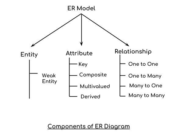
As shown in the above diagram, an ER diagram has three main components:
1. Entity
2. Attribute
3. Relationship
1. Entity
An entity is an object or component of data. An entity is represented as rectangle in an ER diagram. For example: In the following ER diagram we have two entities Student and College and these two entities have many to one relationship as many students study in a single college. We will read more about relationships later, for now focus on entities.
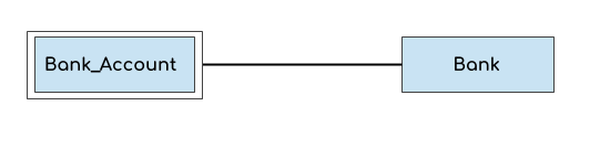
Weak Entity:
An entity that cannot be uniquely identified by its own attributes and relies on the relationship with other entity is called weak entity. The weak entity is represented by a double rectangle. For example – a bank account cannot be uniquely identified without knowing the bank to which the account belongs, so bank account is a weak entity.
2. Attribute
An attribute describes the property of an entity. An attribute is represented as Oval in an ER diagram. There are four types of attributes:
1. Key attribute
2. Composite attribute
3. Multivalued attribute
4. Derived attribute
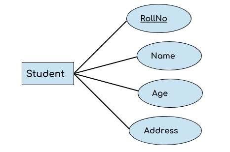
1. Key attribute:
A key attribute can uniquely identify an entity from an entity set. For example, student roll number can uniquely identify a student from a set of students. Key attribute is represented by oval same as other attributes however the text of key attribute is underlined.
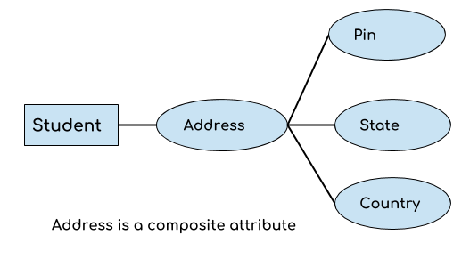
2. Composite attribute:
An attribute that is a combination of other attributes is known as composite attribute. For example, In student entity, the student address is a composite attribute as an address is composed of other attributes such as pin code, state, country.
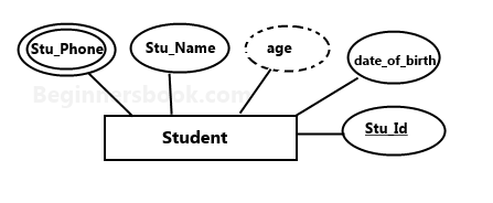
3. Multivalued attribute:
An attribute that can hold multiple values is known as multivalued attribute. It is represented with double ovals in an ER Diagram. For example – A person can have more than one phone numbers so the phone number attribute is multivalued.
4. Derived attribute:
A derived attribute is one whose value is dynamic and derived from another attribute. It is represented by dashed oval in an ER Diagram. For example – Person age is a derived attribute as it changes over time and can be derived from another attribute (Date of birth).
E-R diagram with multivalued and derived attributes:
3. Relationship
A relationship is represented by diamond shape in ER diagram, it shows the relationship among entities. There are four types of relationships:
1. One to One
2. One to Many
3. Many to One
4. Many to Many
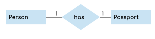
1. One to One Relationship
When a single instance of an entity is associated with a single instance of another entity then it is called one to one relationship. For example, a person has only one passport and a passport is given to one person.
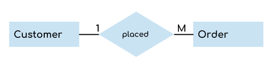
2. One to Many Relationship
When a single instance of an entity is associated with more than one instances of another entity then it is called one to many relationship. For example – a customer can place many orders but a order cannot be placed by many customers.
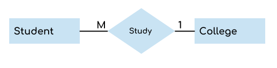
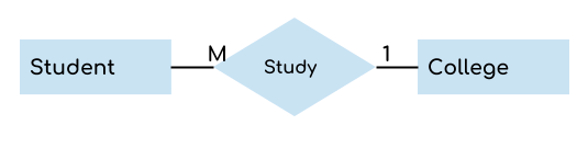
3. Many to One Relationship
When more than one instances of an entity is associated with a single instance of another entity then it is called many to one relationship. For example – many students can study in a single college but a student cannot study in many colleges at the same time.
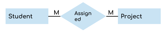
4. Many to Many Relationship
When more than one instances of an entity is associated with more than one instances of another entity then it is called many to many relationship. For example, a can be assigned to many projects and a project can be assigned to many students.
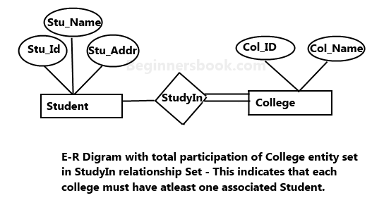
Total Participation of an Entity set
A Total participation of an entity set represents that each entity in entity set must have at least one relationship in a relationship set. For example: In the below diagram each college must have at-least one associated Student.
Leave Comment