NSS (Network Switching Subsystem)
The NSS combines the call rotating switches (MSC and GMSC) with data base
registered required to keep track of subscriber’s movements and use of the system. Key
elements of NSS are:
1. MSC
2. VLR
3. HLR
MSC (Mobile Switching Centre)
The mobile-services switching centre is an exchange which performs all the switching
and signaling functions for mobile stations located in a geographical area designated as
the MSC area. These are high performance digital ISDN switches. It is used for
connection between mobile phone to mobile phone within same network. It is used for
connection between mobile phone to fixed phone within a network. It manages BSC
within a geographical area
GMSC (Gateway MSC)
Connection for another network MSC handles all the signaling needed for connection set up and connection release.
HLR (Home Location Register)
The HLR is a centralized network data base that stores and manages all mobile services belonging to a specific operator. It acts as a permanent store for a person’s subscription information until that subscription is cancelled. It provides call routing and roaming facility by combining with MSC and VLR. It is considered as a Database which stores the information about the subscriber within covering area of MSC. Information includes current location of the mobile & all the service providing information, when a phone is powered off this information is stored in HLR. It is also a database but contains a temporary copy of some of important information stored in HLR. If a new MS user comes into location area, then VLR will provide relevant information by bringing it from HLR.
VLR (Visitor Location Resister)
It is a temporary storage device of GSM network. It stores subscribers’ subscription information for MS which are within the particular MSC service Area. There is one VLR for each MSC service area
OSS (Operation and Support Subsystem)
It contains necessary function for network operation and maintenance.
Key Elements are
1. OMC
2. EIR
3. AUC
OMC (Operation and maintenance center)
It is connected to different components of NSS & to BSC. It controls the traffic load of BSS.
EIR (Equipment Identity Register)
A database that contains a list of all valid mobile equipment within the network where each MS is identified by IMEI (International Mobile Equipment Identity).EIR contains a list of IMEI of all valid terminals. An IMEI is marked invalid if it is stolen. EIR allows the MSC to forbid calls from this stolen terminal. The equipment identification procedure uses the identity of the equipment itself (IMEI) to ensure that the MS terminal equipment is valid.
AUC (Authentication Center)
It is defined to protect user identity & transmission. It is a protected database and stores a copy of secret information stored in SIM card .These data help to verify user’s identity.
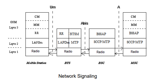
Network Signaling
Abbreviations
LAPD Link Access Procedure D-Channel Managed
RR: Radio Resource
MM: Mobility Management
CM: Call Management
BTSM: BTS MAnagement
BSSMAP: BSS Application Protocol
SCCP: Signaling Connection Control Part
The signaling protocol in GSM is structured into 3 layers.
1. Layer1 Physical Layer
2. Layer2 Data Link Layer
3. Layer3 Network Layer
MS BTS
The physical layer between MS & BTS is called Um interface. It performs following
functions
1. Full or half duplex access.
2. Provides TDMA, FDMA, and CDMA.
3. Framing of data.
The data link layer controls the flow of packets to and from network layer and provides
access to various services like:
Connection: Provides connection between two terminals.
Teleservices -Services offered by a mobile network to users like: MMS, SMS,
etc
The data link layer present between MS & BTS is LAPDm (Link Access Protocol
managed). LAPDm protocol describes the standard procedure in GSM for accessing Dchannel Link.
Its functions are:
1. Dataflow control.
2. Acknowledged / unacknowledged data Transmission.
3. Address and sequence no. check.
3. Segmentation.
The network layer has 3-sublayers
CM (Call Management)Supports call establishment, maintenance, termination. It supports SMS. Support DTMF (Dual Tone multiple frequency) signaling.
MM (Mobility Management)
Control the issue regarding mobility Management, location updating & registration.
RRM (Radio Resource Management.)
It manages radio resources such as: frequency assignment, signal measurement.
BTS BSC signaling protocols
The physical layer between BTS & BSC is called Abis interface, where voice is coded by using 64kbps PCM. The connection between BTS and BSC is through a wired network. The data link layer is LAPDm. Network Layer protocol is called BTS Management which interact with BSSAP.
BSC MSC signaling protocol
Physical layer between BSC & MSC is called U interface. Data link layer protocol between BSC & MSC is MTP (Message Transfer Protocol) & SCCP (Signaling Connection Control Protocol). MTP and SCCP are part of the SS7 (Signaling System No7) used by interface A. NETWORK layer protocols at the MSC are CM, MM and BSSAP (Base Subsystem Application Part).
Leave Comment